Launch
April 2020 - March 2021
|
|
Launch Stats:
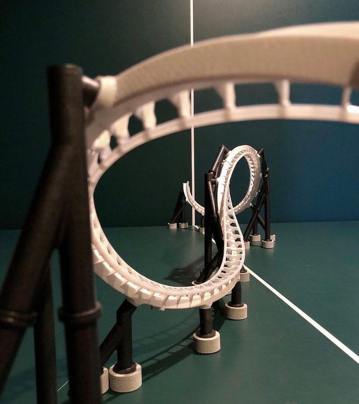
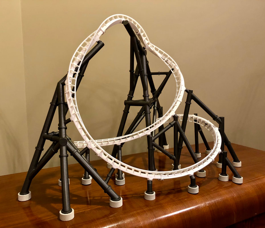
1:35 scale Track Gauge: 26mm Dimensions: 1.8m x 1m x 0.8m (LWH) Number of components: 2983
Design Time: ~600h Print Time: ~800h Post Processing Time: ~35h Assembly Time: ~100h Printer: Creality CR-10 Nozzle Diameter: 0.4mm |
|
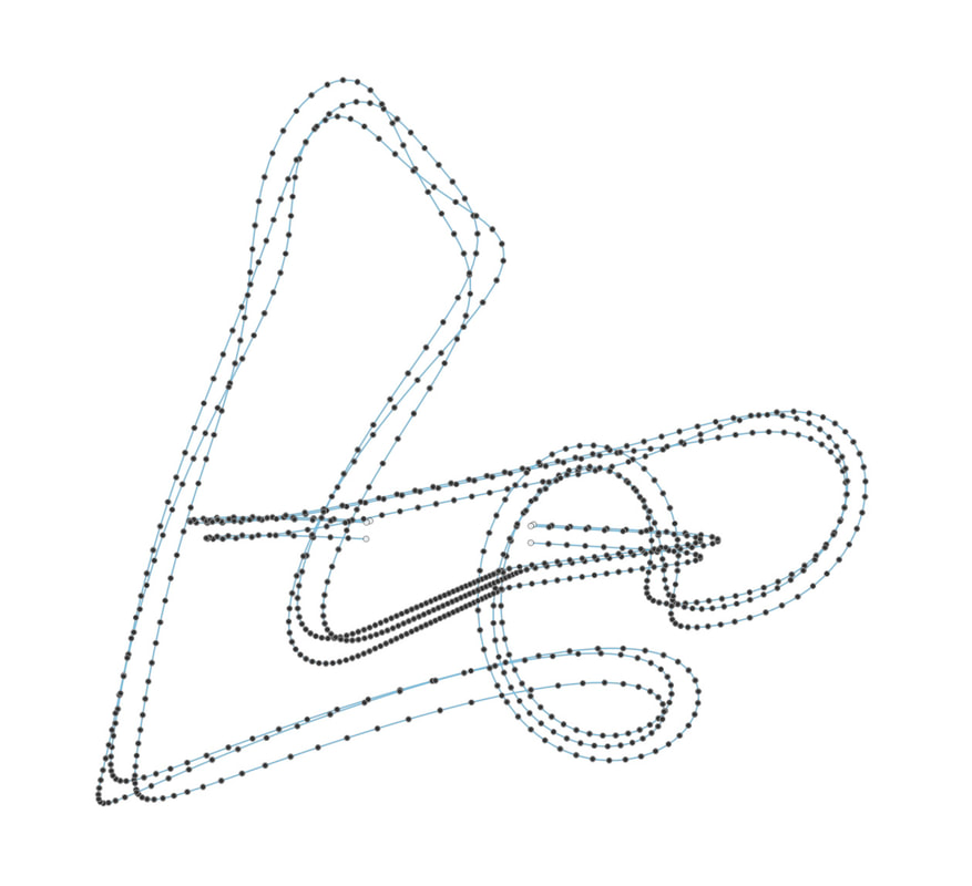
The entire process begins with the layout design in NoLimits2.
Being a large scale proof of concept model, a relatively small and simple custom design was decided on.
The 3D coordinates of the track points were saved from NL2 and imported into Fusion 360.
|
|
|
Tube Slicing:
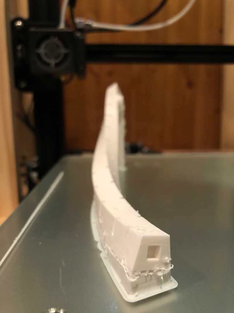
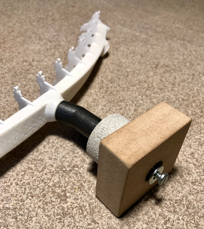
Options for pre-sliced tubing were limited, so another type had to be used. For material property and scaling reasons, 4mm OD PTFE tubing was chosen as the rail. A jig holding 2 razor blades was designed and printed to slice the tubing at a precise angle that allowed the rail to snap securely onto the track ties. Download a .stl of the slicer below if you'd like to try building your own 3D printed roller coaster!
|
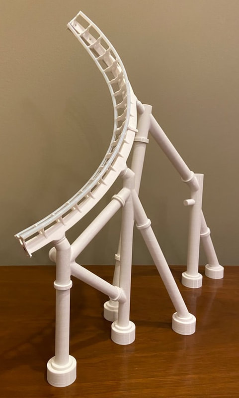
Track and columns were set up for an initial test fit, dismantled for painting, and put together once again prior to final assembly.
|
Brake Run:
The train is stopped at the end of the layout through the use of friction fins that interfere with extrusions on the undercarriage of the train. Using essentially a 4 bar linkage system, a rubber band provides an upward force that the train opposes as it enters the brakes. A servo motor disengages the fins by pulling them downward until the train leaves the zone.
|
|
|
|
Design of the Launch:
A micro servo motor initiates the sequence by actuating a switch that turns on a DC motor. Through geared transmission, the motor spools up a cable that is connected to a catch car that latches onto the underside of the train. On the other end of the catch car, a bungee is attached that extends around two U groove bearings and underneath the base. Once fully retracted, the catch car triggers a limit switch that causes the DC motor to turn off.
When ready to launch, a second servo motor disengages an idler gear from the transmission that allows the spool to spin freely and the bungee to return to its original position, in turn launching the vehicle down the length of the track.
|
|
|
|
Station construction entailed designing functional gates, drive tires, and included housing the launch mechanics.
Footers and columns were installed, followed by the track and station.
Nearly 10 hours of troubleshooting and refining the code of the control system rounded out the completion of the project.
Final pictures of Launch fully assembled.
