
Test Track I
March 2021
|
|
Track Specs:
1:35 scale Track Gauge: 26mm Length: 575mm Width: 210mm Height: 116mm Number of components: 145
Design Time: 20h Print Time: 45h Post Processing Time: 2h Assembly Time: 1.5h Printer: Creality CR-10 Nozzle Diameter: 0.3mm |
|
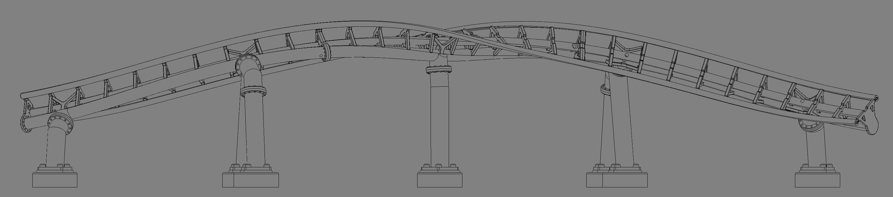
This was the first iteration of developing a new track type for the layout following Launch.
Taking inspiration from Intamin's newer generation double backbone track, these two spines have varying diameters of 5.5mm and 8mm for the top and bottom respectively.
With standoffs holding the two spines together, track ties attach to both backbones with three total points of contact, increasing the overall rigidity while ensuring the rail spline points are met to guarantee maximum smoothness.
|
|


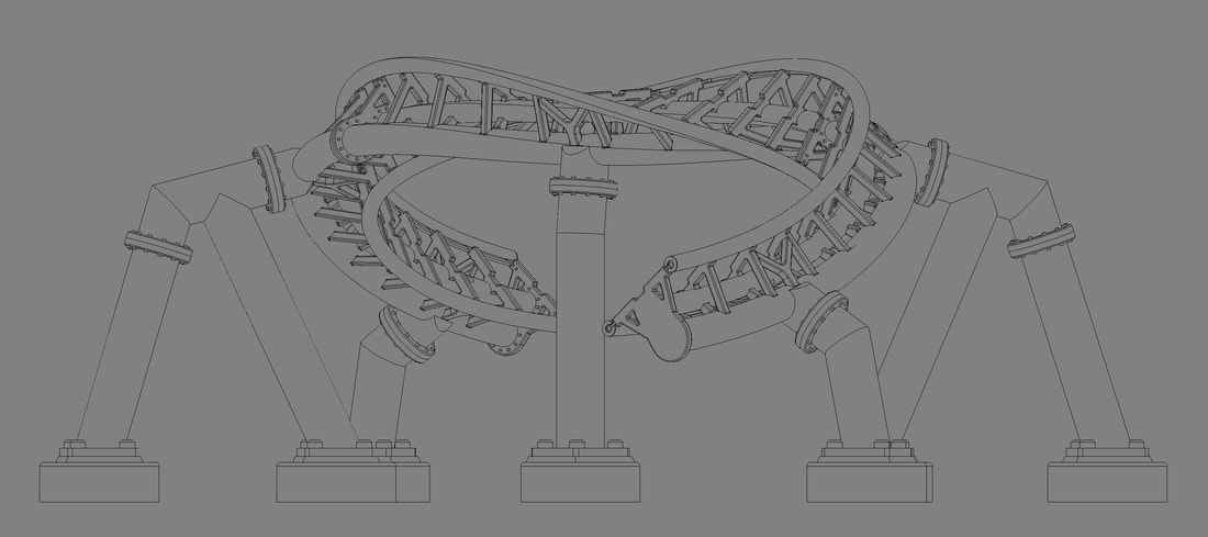
Track to Track:
The above track to track connections were redesigned for increased simplicity in assembly. Rather than using 2 removable plates, 2 screws, and 2 nuts for each attachment like in the first track type, the improved second iteration uses a male-female connection with only one screw to fasten the sections together.
The above track to track connections were redesigned for increased simplicity in assembly. Rather than using 2 removable plates, 2 screws, and 2 nuts for each attachment like in the first track type, the improved second iteration uses a male-female connection with only one screw to fasten the sections together.


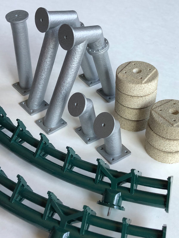
Track to Column:
Track to column connections were slightly reimagined to allow for the double backbone track design. Because the top spine is so small in diameter, it was not possible to accommodate a thru hole large enough for a M2 screw head, resulting in the design choice to permanently house the screw within the thicker bottom spine. A thru hole for a small screwdriver was placed in the top spine for installation of the section. Finally, greater realism was introduced over the previous generation by adding flanges on the track and column connections, as well as including a Y brace at each connection point.
Track to column connections were slightly reimagined to allow for the double backbone track design. Because the top spine is so small in diameter, it was not possible to accommodate a thru hole large enough for a M2 screw head, resulting in the design choice to permanently house the screw within the thicker bottom spine. A thru hole for a small screwdriver was placed in the top spine for installation of the section. Finally, greater realism was introduced over the previous generation by adding flanges on the track and column connections, as well as including a Y brace at each connection point.
Column to Column:
Column to column connections remained unchanged in the overall redesign as they functioned simply and strongly enough on the Launch layout. The only update was the improved detail of small circular bolts on each flange.
Column to column connections remained unchanged in the overall redesign as they functioned simply and strongly enough on the Launch layout. The only update was the improved detail of small circular bolts on each flange.
|
Although it appears more complex, this design was simplified to take 1 hour less to complete the construction of a single track section when compared to the print, post processing, and assembly time of the original trapezoidal track used on Launch.
|
|
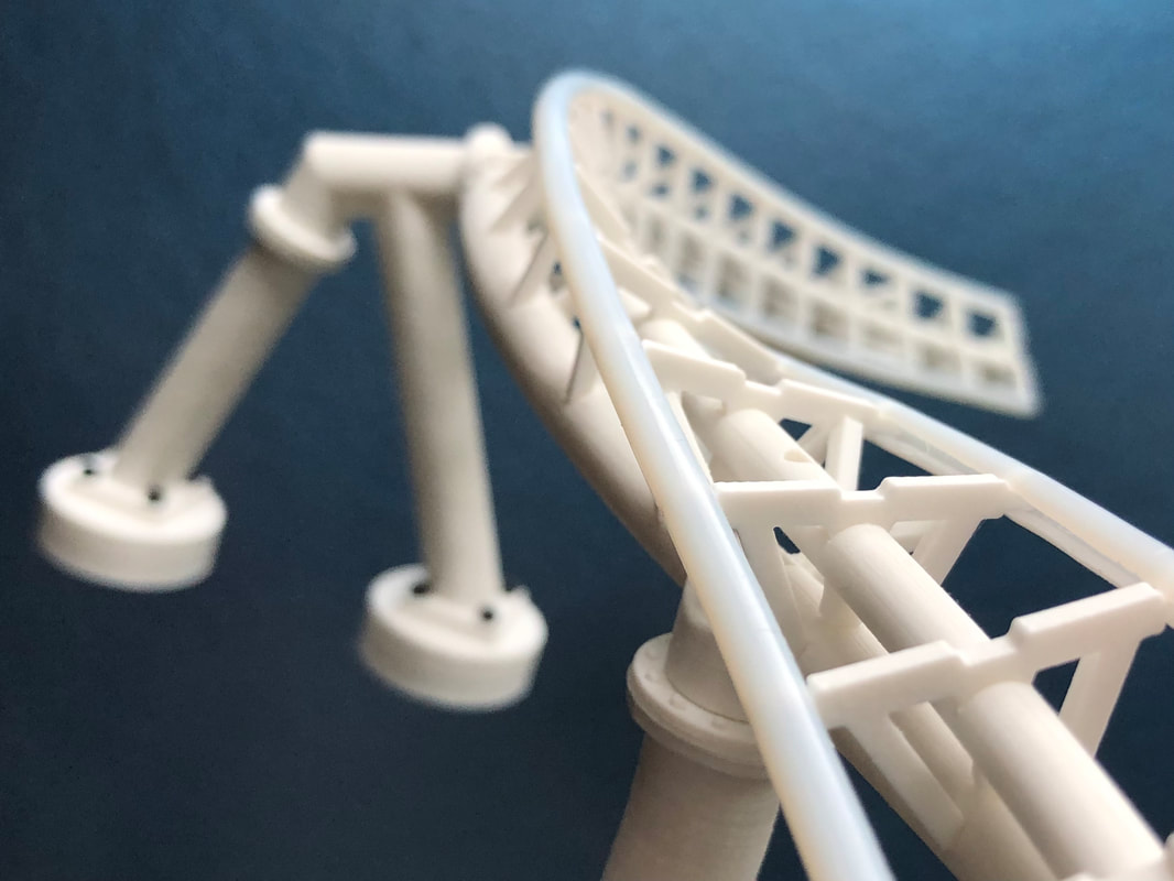
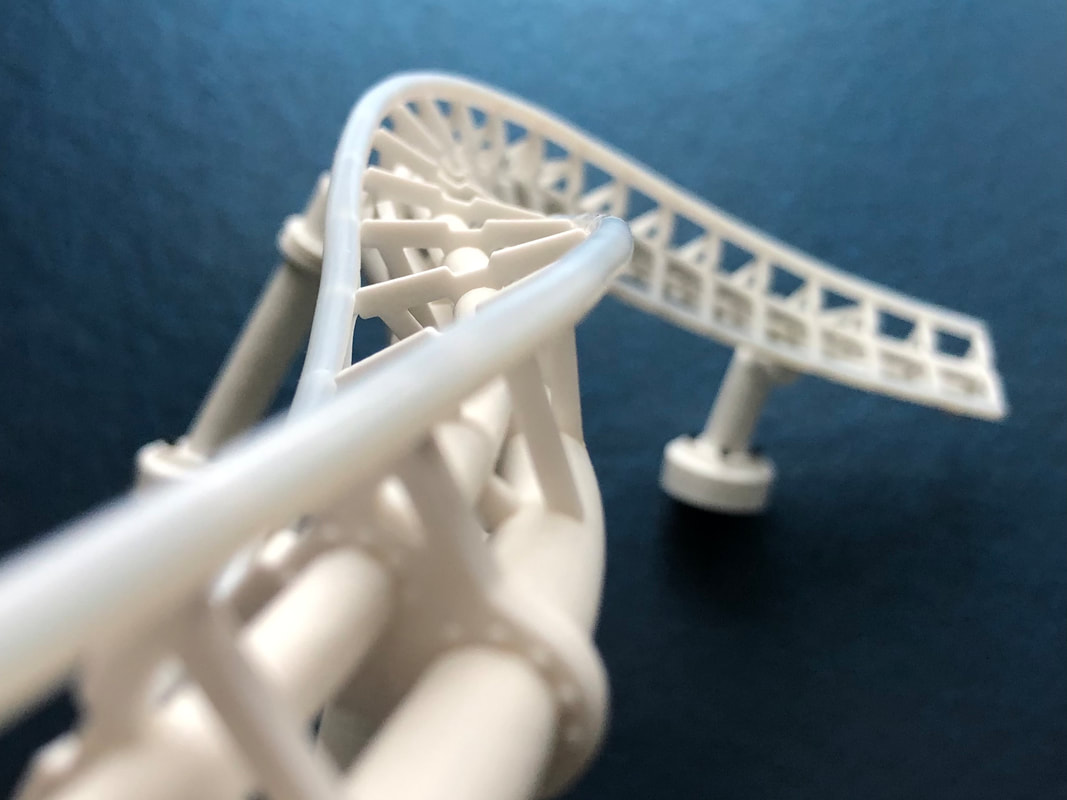
After all the parts were put together, the assemblies were painted their respective colors. Unfortunately the PTFE tubing used for rails was not available in a wide variety of colors, so some of the white tubing from Launch was recycled and used on this track.
To connect the supports to the footers, a new technique was used that fastened the base of each column with four M2x6s. In theory, this would allow each footer to be fastened to a base independently of the supports. However, in practice, it was far too tedious to screw in four fasteners per support when the previous method simply used one screw going through the base, footer, and into the bottom of the column.
|
|
